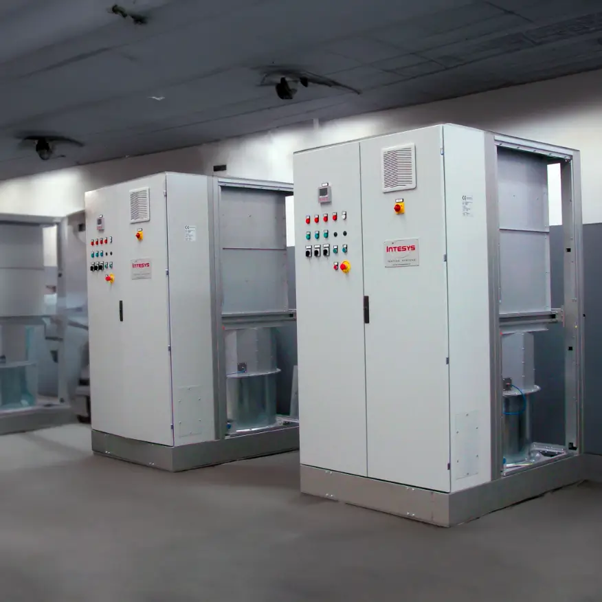
Customised load banks and test benches from 10 kW to 1 MW for testing and operation of gensets, electric generators, UPS, cogeneration systems, wind generators and photovoltaic systems.
Passive and active regenerative load banks and test benches for the testing and operation of generator sets, electric generators, UPS, cogeneration systems, wind generators and photovoltaic systems
Discover More
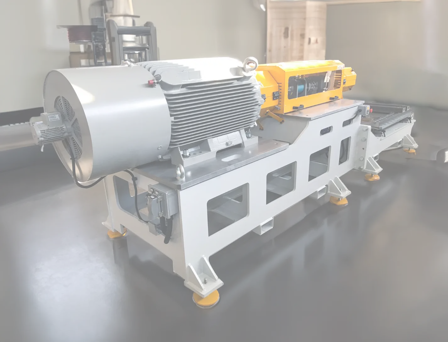
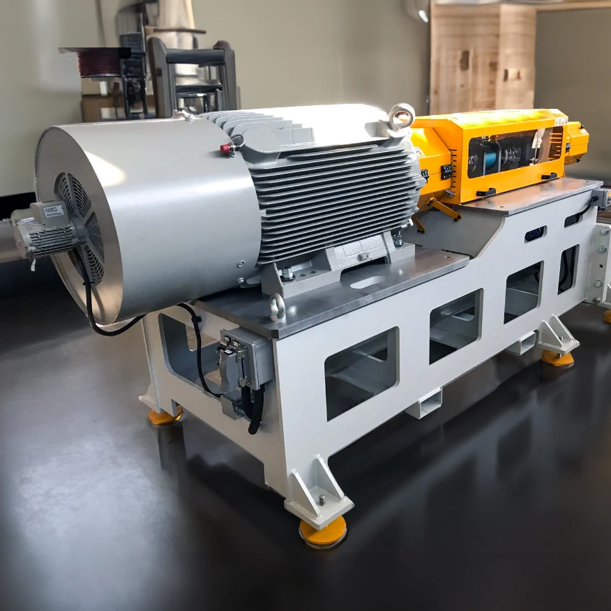
MotorTest
Active regenerative brake benches for testing electric motors, joint drives, inverters, gearboxes and inverters.
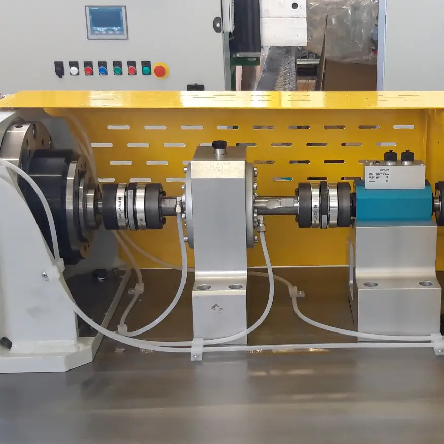
StarterTEST HS-28400 allows running/testing of 28Vdc 400 A starter generators, from 0 RPM up to 12000 Rpm: speed, current, voltage, direction of rotation.