Intesys Load Banks:
Complete and Autonomous Solutions for
the Electrical Test and Measurement
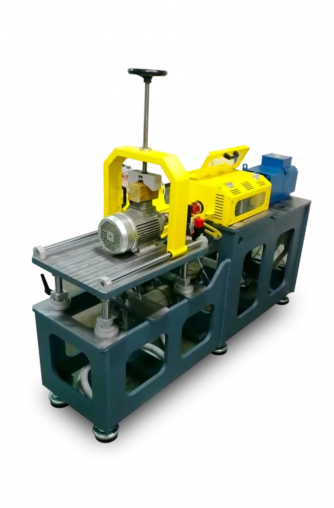
Intesys load banks are complete, self-contained units equipped with the inductive and/or resistive load elements, the ventilation system, overtemperature and lack of ventilation protection, load circuit protection, load control devices and systems, digital instruments for measuring ac and dc quantities, and the computerised system + GenTest software for automatic testing and data collection.
To test and maintain generator sets, gas turbines, UPSs, alternators
To reduce excessive emissions from underloaded diesel generators
To extend the life of endothermic engines
In compliance with European and US testing standards (ISO8528, IEC364-7-710, EN60034-9, NFPA70, NFPA110)
Manufacturers of power systems such as generator sets, UPSs and battery systems for computerised laboratory and end-of-line testing;
Buildings, hospitals, public gathering places, critical communications, IT and financial security systems equipped with emergency power systems: European and US standards require that these be regularly maintained by load testing at at least 50 per cent of rated power and that data be collected;
Any stationary genset: to avoid the common problem of ‘wet stacking’ when the diesel engine runs at insufficient load causing unburnt fuel to accumulate in the exhaust system, which can interfere with injectors, engine valves and the exhaust system, including turbochargers, thereby reducing performance; The appropriate load can be achieved by providing an additional load by means of a resistive load bank equipped with an automatic load control device; this increases the service life of the diesel engine by up to four times and increases its efficiency;
UPS and battery power systems: load banks maximise the life of batteries by charging and discharging them regularly;
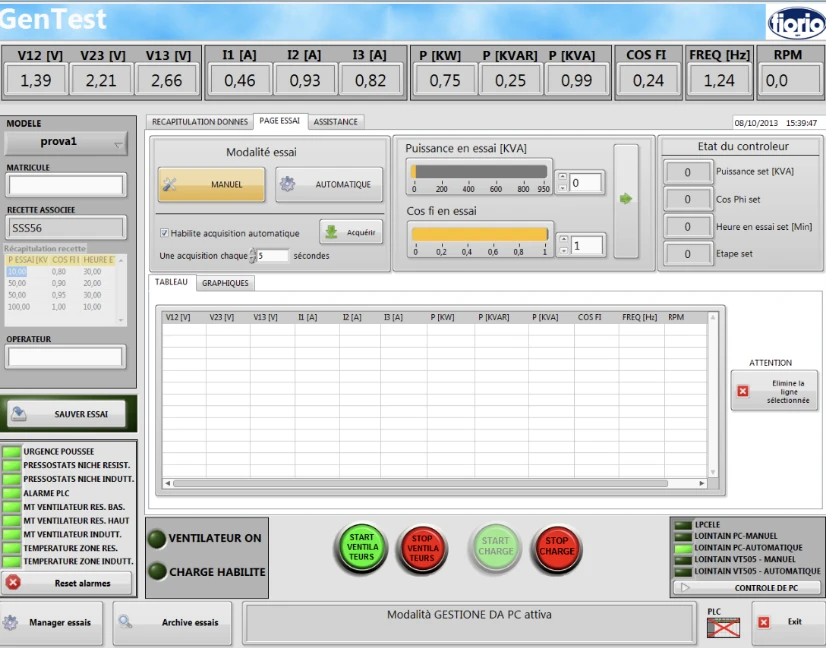
Software GenTest
LabVIEW®
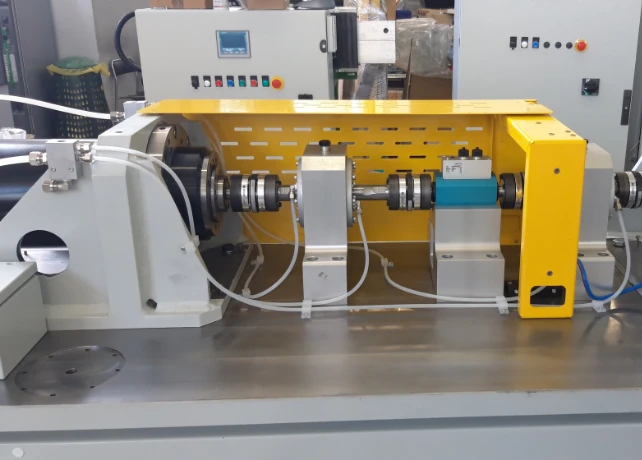
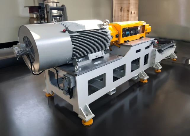
MotorTEST LabVIEW® is software that enables the complete characterisation of electric motors on motor brake benches and is compatible with a wide range of market-standard control/data acquisition systems and instrumentation
Detectable quantities: motor speed, torque, power output, voltages, currents, absorbed and apparent power, power factor, efficiency, slip, mains frequency, motor winding resistances, temperatures
Motor and brake registration data archive: database in MS Access format into which the operator enters both the test bench settings and the registration data of the engines to be tested; The parameters selected before testing will automatically set the inverter configuration of the braking motor and the inverter configuration of the motor to be tested (high-frequency motors)